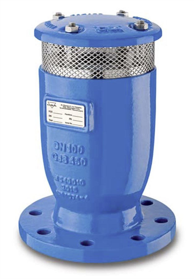
AVK AIR RELIEF VALVE, RAPID FILL PREVENTION, EN1092, 16-40 BAR
Lynx 3F-RFP, red. bore, clean water, A2 bolts, Delta Seal GZ A4 nuts fasteners, 250µm blue RAL5005 EP coating

Contact
Chan Chee Leong
Senior Manager, Sales and Marketing
Air relief valve for clean water and neutral liquids to max., 70°C. Used in applications as transmission lines, water distribution networks and for irrigation.
AVK air releaf valve, rapid fill prevention valve with large oriface ensure a controled filling operation of the pipeline network by adjusting the air outflow capacity. Further it has been designed to allow release of air pockets accumulated under working conditions, the entrance of large volumes of air during draining operations and pipeline bursts and the air discharge with controlled speed, to prevent water hammer. The valve are generally used near pumps, where there are changes in slope ascending and at high points where the pipeline is subjected to water hammer.
| Variant 861/12-001 | |
|---|---|
| Connection: | No connection type specified |
| Material: | Ductile iron |
| DN: | DN50 - DN400 |
Features
- The rapid filling preventer automatically adjust the outflow capacity thereby reducing the velocity of the incoming water column and minimizing the risk og wter hammer. Uncontrolled filling operations and transient events will inevitably generate the rapid closure of the air valves installed in the system with consequent damages. This type of valve will minimize the risk of this occurring.
- The spray effect during closing and the risk of drowning are reduced compared to standard combination air valves.
- Single chamber body in ductile cast iron, is provided with intenal ribs for a consistant and accurate guiding of the mobile block.
- Mobile block composed of a main float and upper disc, joined together by the air release system in AISI 316, and a additional anti surge obturator.
- Nozzle and gasket holder are wear resistant due to the gasket compression control.
- Cover in ductile iron and sreen in stainless steel prevents materials and insects entering the valve. Outlet for submerged applications are optional.
- Working conditions 0,2 - 40 bar differential pressure
Downloads
Reference nos. and dimensions:
| Reference no. | Gross Price MYR |
DN mm |
Flange drilling |
PN Class |
L mm |
H3 mm |
Theoretical weight/kg |
Notes |
|---|---|---|---|---|---|---|---|---|
| 861-0050-12-0111 | 2,726 | 50 | PN16 | PN16 | 165 | 236 | 7.0 | |
| 861-0050-12-0911 | 2,490 | 50 | 117 | 231 | 5.0 | 2" BSP thread | ||
| 861-0080-12-0111 | 3,604 | 80 | PN16 | PN16 | 210 | 305 | 11 | |
| 861-0100-12-0111 | 4,979 | 100 | PN16 | PN16 | 235 | 303 | 14 | |
| 861-0150-12-0111 | 6,551 | 150 | PN16 | PN16 | 305 | 337 | 23 | |
| 861-0200-12-0111 | 12,578 | 200 | PN16 | PN16 | 375 | 515 | 55 | |
| 861-0250-12-0111 | 22,955 | 250 | PN16 | PN16 | 450 | 625 | 101 | |
| 861-0300-12-0111 | 38,454 | 300 | PN16 | PN16 | 485 | 735 | 127 | |
| 861-0350-12-0111 | 60,387 | 350 | PN16 | PN16 | 580 | 850 | 251 | |
| 861-0400-12-0111 | 91,700 | 400 | PN16 | PN16 | 660 | 995 | 304 |
Components
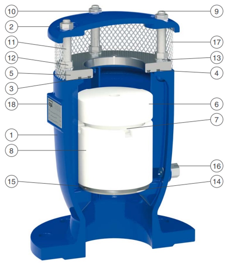

| 1. | Body | Ductile iron EN-GJS-500-7 |
| 2. | Cap | Ductile iron EN-GJS-500-7 |
| 3. | O-ring | NBR rubber |
| 4. | O-ring | NBR rubber |
| 5. | Seat | Stainless steel AISI 304 |
| 6. | Disc | Polyethylene |
| 7. | Nozzle | Stainless steel AISI 316 |
| 8. | Float | Polypropylene |
| 9. | Studs | Stainless steel A2 |
| 10. | Nuts | Stainless steel A2 |
| 11. | Spacer | Stainless steel A2 |
| 12. | Nuts | Stainless steel A2 |
| 13. | Washer | Stainless steel A2 |
| 14. | Disc | Stainless steel AISI 304 |
| 15. | Screw | Stainless steel A2 |
| 16. | Drain valve | Stainless steel AISI 303 |
| 17. | Screen | Stainless steel AISI 304 |
| 18. | Label | Stainless steel AISI 304 |
Test/Approvals
- Hydraulic test according to EN 1074-1 and 4 / EN 12266
- Approved according to EN 1074-1 and 4
Standards
- AWWA C512, EN 1074-4
- Flange drilling to EN1092, PN10/16/25/40